










Exhaust Fan Control Panel for Poultry Shed: Wiring Diagram & Parts List (Pakistan)


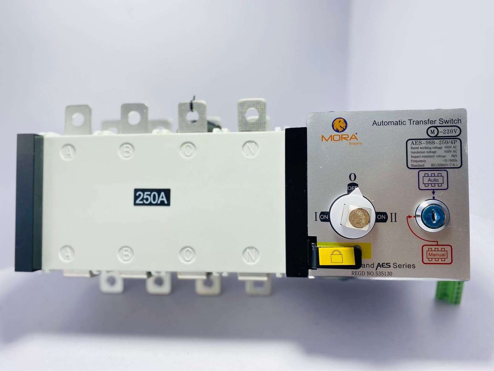
Short answer: an exhaust fan control panel for a poultry shed should give every fan its own set of three parts: a 3-pole MCB for short-circuit protection, a motor-rated (AC-3) magnetic contactor to switch it, and a thermal overload relay set to the motor’s nameplate current. All contactor coils run from one 230 V control circuit with a Hand-Off-Auto selector, so the climate controller switches the coils (never the motors), and an on-delay timer staggers the fans when WAPDA or the generator comes back. A three-phase voltage/phase protector, an ATS and an SPD at the incomer complete the panel. For a typical 1.1 kW (about 2.5 A) exhaust fan, a 9 A AC-3 contactor and a 2.5–4 A overload range are a comfortable fit.
Many control-shed breakdowns are not really a “bad fan” problem. They start in the panel: one overload protecting four motors, a controller relay burnt because it was switching fan current directly, or ten fans starting together the moment power returns after load-shedding and stalling the generator. This guide explains how a proper exhaust fan control panel is built, with an original power diagram, a contactor wiring diagram for the control side, a sizing table by fan motor size and a worked example for a 10-fan shed.
If you have not yet worked out the total load, main breaker and generator size, start with our poultry shed electrical load calculation guide. This post picks up from there and focuses only on the fan control panel itself.
What goes inside an exhaust fan control panel for a poultry shed
An EC (environment-controlled) shed panel, also called a poultry farm control panel, has two separate parts:
- Power circuit (400 V three-phase): incomer, ATS, main breaker, protection devices, busbar, and one motor branch per fan or pump.
- Control circuit (230 V, single phase + neutral): contactor coils, selector switches, the climate controller’s relay outputs, timers, indicator lamps and alarms.

Keeping the two parts separate is what makes the panel safe and easy to fault-find. The controller only ever sees a small coil current, the motors only ever see a contactor, and every fan can be switched by hand if the controller fails.
Per-fan parts list (one motor branch)
| Part | Job in the panel | How to choose it |
|---|---|---|
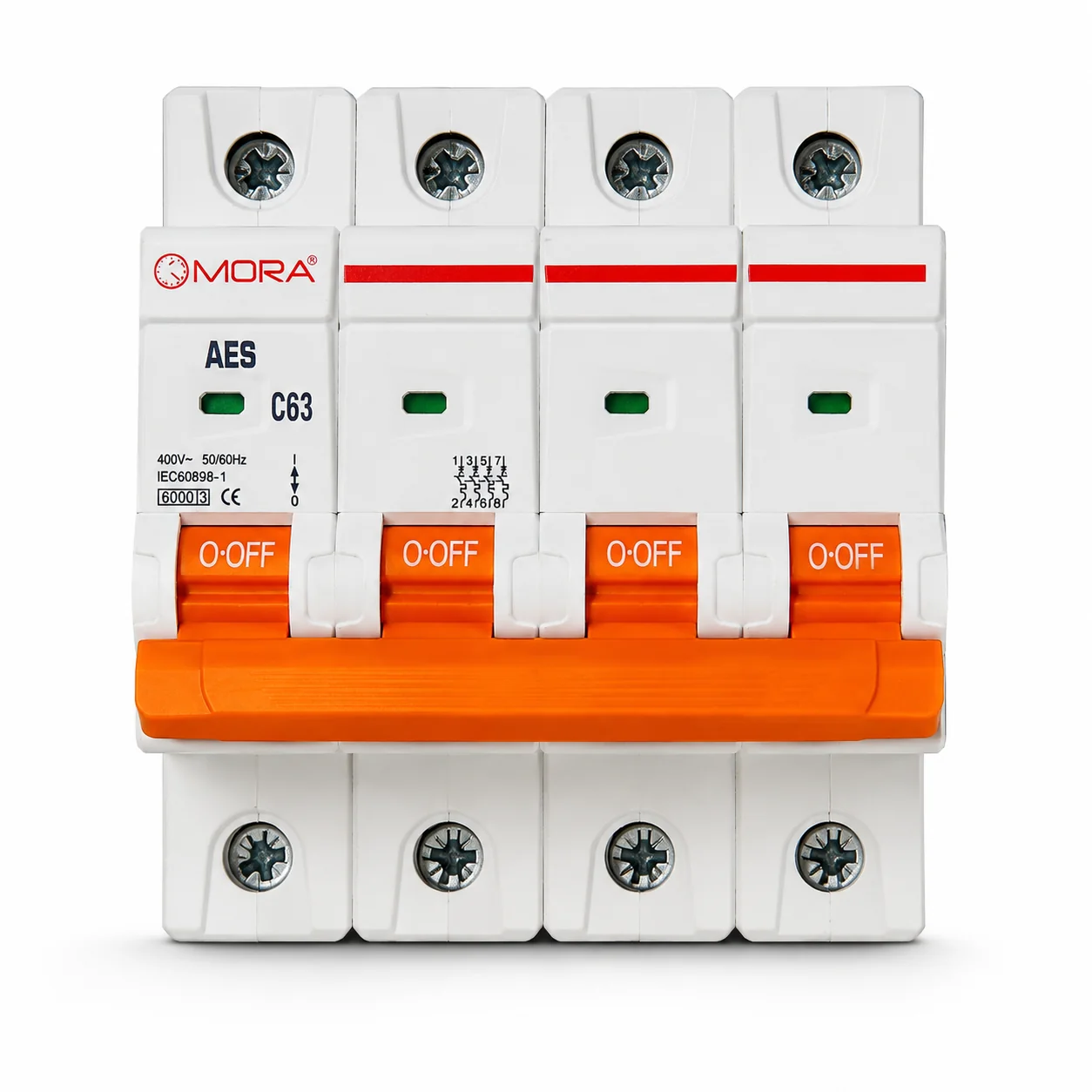
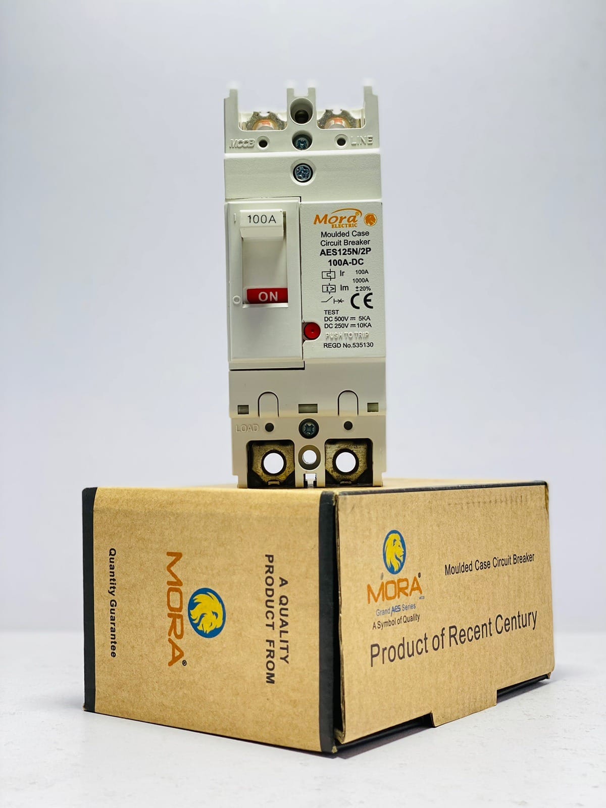
| 3-pole MCB (D or C curve) | Short-circuit protection for the fan cable and motor | Must not trip on starting current; D-curve gives more margin for motors |
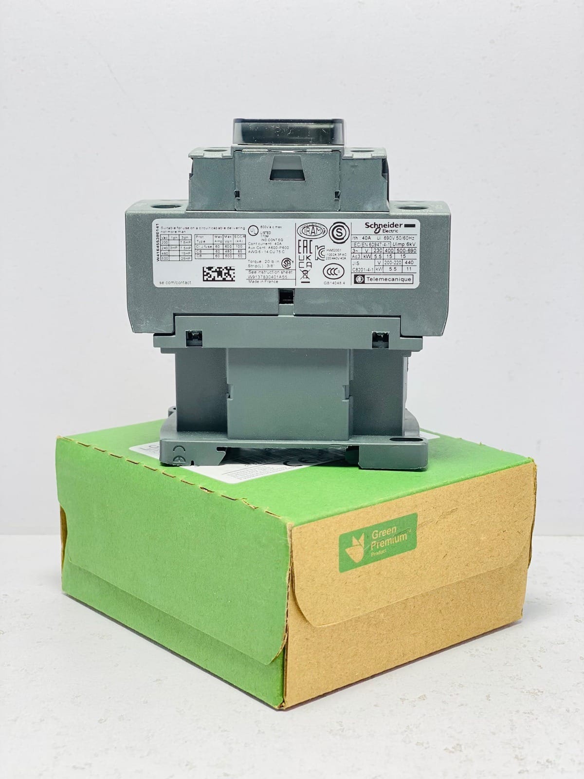
| Magnetic contactor | Switches the fan on and off many times a day | AC-3 rating above the motor current; coil voltage matching your control circuit (220–230 V AC is common) |
| Thermal overload relay | Trips on overload, jammed blade or single phasing | Adjustable range that covers the nameplate full-load current (FLC); set dial to FLC |
| Hand-Off-Auto selector | Lets staff run the fan by hand if the controller fails | One per fan or per fan stage |
| Run and trip lamps | Shows at a glance which fan is running or tripped | 22 mm LED indicators, green = run, amber/red = trip |
| On-delay timer (optional per stage) | Staggers restarts after load-shedding | Few seconds per fan or group; many controllers have this built in |
Alternative: a motor protection circuit breaker (MPCB) combines the MCB and overload in one device with an adjustable current dial. It costs more per fan but saves space and wiring in large panels.
Contactor and overload sizing table by exhaust fan size
The table below uses typical full-load currents for 4-pole, 400 V three-phase motors. Real values vary by make and efficiency class, so always read the current (A) on your fan motor’s nameplate and use that.
| Fan motor | Typical FLC at 400 V | Contactor (AC-3), one fan | Overload range to cover FLC | Branch MCB (3P, D curve) |
|---|---|---|---|---|
| 0.75 kW (1 HP) | about 1.9 A | 9 A (e.g. LC1D09) | 1.6–2.5 A | 6 A |
| 1.1 kW (1.5 HP), common 50-54 inch fan | about 2.6 A | 9 A (e.g. LC1D09) | 2.5–4 A | 6 A |
| 1.5 kW (2 HP) | about 3.5 A | 9 A | 2.5–4 A | 6 A |
| 2.2 kW (3 HP) | about 5 A | 9–12 A | 4–6 A | 10 A |
| 3 kW (4 HP) | about 6.6 A | 12–18 A | 5.5–8 A | 10 A |
Why the contactor looks “oversized”: a contactor’s AC-3 rating is for starting and stopping squirrel-cage motors under the IEC 60947-4-1 standard for contactors and motor-starters. A 9 A AC-3 contactor will happily switch a 2.6 A fan, and the extra headroom means cooler contacts and longer life. For minimum-ventilation fans that a timer switches on and off all day in winter, going one size up (for example a Schneider LC1D18 18 A contactor on a 3 kW fan) is a cheap way to cut contact wear.
One overload per motor, not per group
Many local panels put two or four fans on one contactor to save money. That can work for switching, but a single overload relay cannot protect each motor properly. If one of four 2.5 A fans jams and draws 5 A, the group current rises from 10 A to 12.5 A, which may still sit inside the overload’s setting, so the jammed motor slowly burns. If you must group fans on one contactor, give each motor its own overload or MPCB and wire all their trip contacts in series with the shared coil.
Exhaust fan contactor wiring diagram (control circuit)
This is the part most competitors skip. The diagram below shows the control side for one fan; repeat the same rung for every fan, sharing the same live and neutral rails.

Step-by-step wiring logic
- Control supply: take one phase and neutral through a 2-pole MCB (a small rating, as used for control circuits) so a coil short cannot take out the whole panel.
- Safety chain in series: emergency stop (NC), then the phase-failure relay contact, then the overload’s NC contact 95-96. If any of these opens, the coil drops and the fan stops.
- Hand-Off-Auto selector: in Hand, live goes straight to the coil; in Off, nothing; in Auto, live passes through the controller’s relay output (or a thermostat) first.
- Stage timer: an on-delay timer contact before the coil gives this fan its own restart delay.
- Coil A1-A2: A1 from the chain, A2 to neutral. The coil voltage printed on the contactor must match your control voltage.
- Indicators: green lamp through the contactor’s auxiliary NO contact (13-14) for “running”; amber lamp through the overload’s NO contact 97-98 for “tripped”; a hooter or red lamp on the phase relay’s alarm contact.
Why the controller must switch only the coil: climate controllers and digital thermostats have small relay outputs meant for coils, not for motor starting current. Wiring a fan motor directly to a controller output is the fastest way to weld or burn that relay. If an output is too weak even for your coil, add a small interposing relay.
Worked example: 10-fan control shed in Pakistan
Let’s build the panel for an example EC shed: 8 tunnel fans + 2 sidewall (minimum ventilation) fans, all 1.1 kW three-phase with a nameplate current of 2.5 A, plus 2 cooling-pad pumps of 0.75 kW (about 1.9 A each). Supply is LESCO three-phase 400 V with a diesel generator as backup.
| Item | Quantity | Rating chosen | Reason |
|---|---|---|---|
| Fan branch MCB, 3P D-curve | 10 | 6 A | Rides through DOL starting current of a 2.5 A motor |
| Fan contactor, AC-3, 220 V coil | 10 | 9 A (sidewall fans: 12 A for frequent cycling) | 2.5 A motor, long contact life |
| Fan overload relay | 10 | 2.5–4 A range, dial at 2.5 A | Set to nameplate FLC |
| Pump branch (MCB / contactor / overload) | 2 sets | 6 A / 9 A / 1.6–2.5 A at 1.9 A | Same logic as fans |
| Hand-Off-Auto selectors + run/trip lamps | 12 sets | 22 mm | Manual override and quick fault view |
| Control MCB, 2P | 1 | Small control rating | Protects coils, lamps, timers |
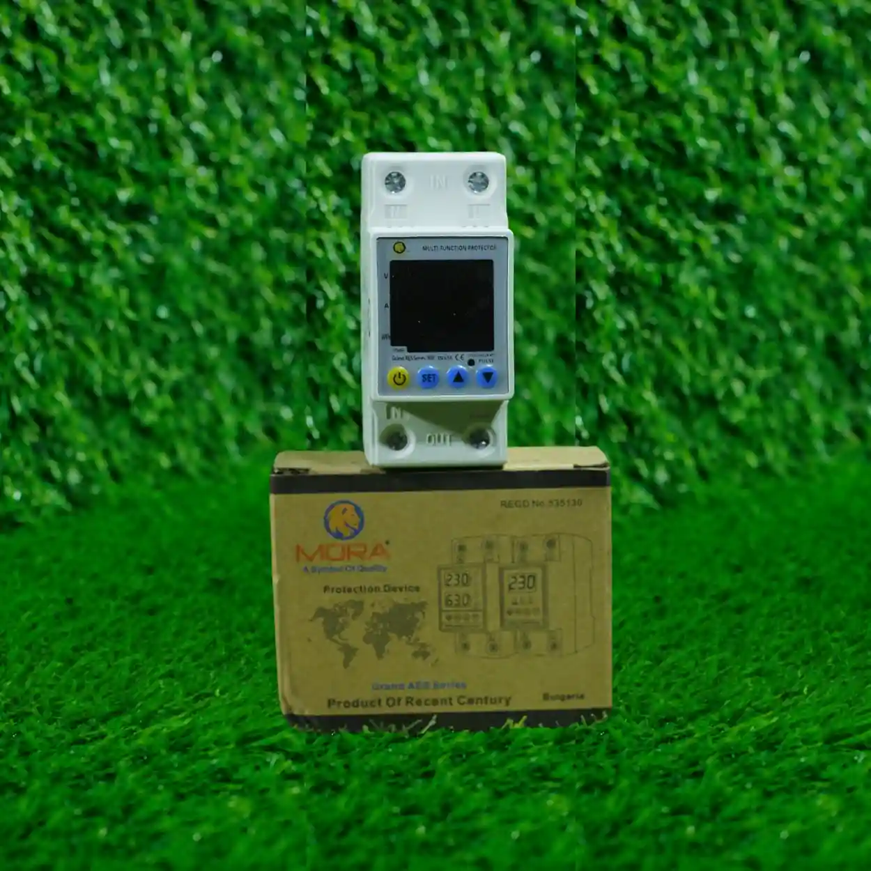
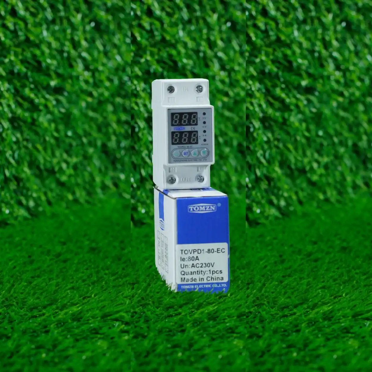
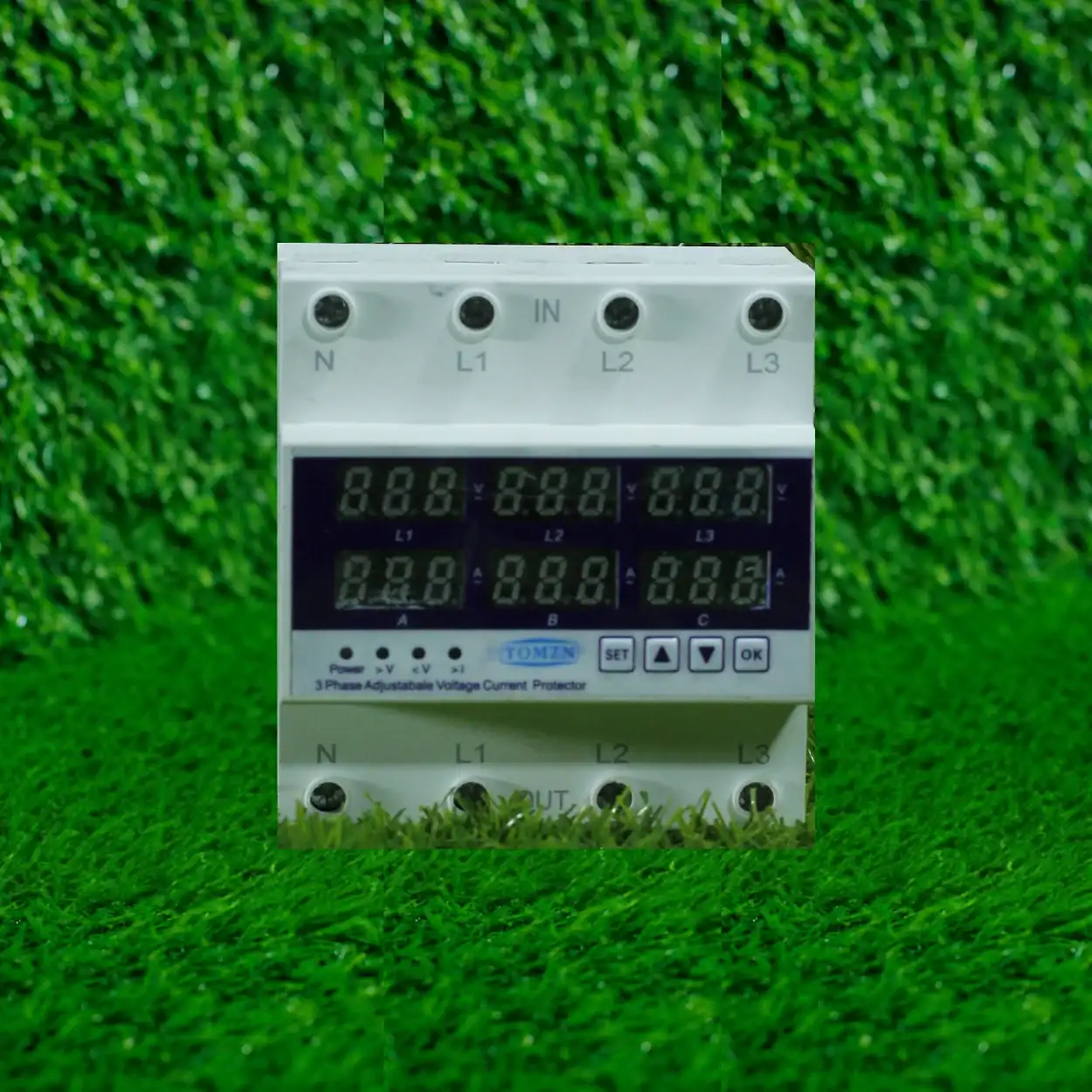
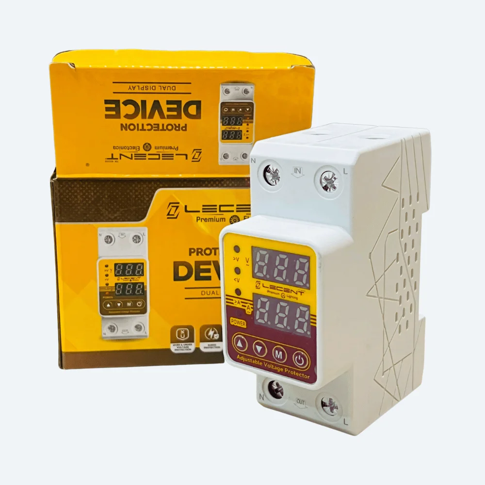
| Phase failure / 3-phase V/A protector | 1 | Sized to the incomer | Stops all motors on single phasing or bad voltage |
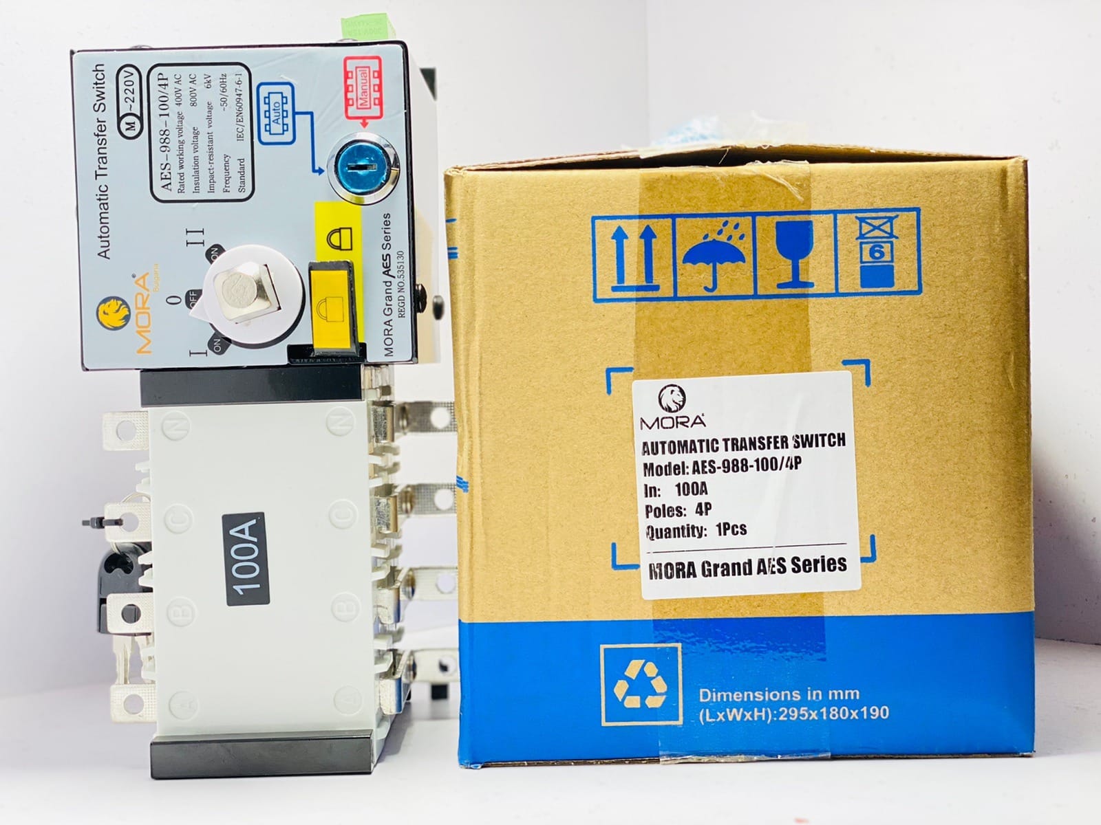
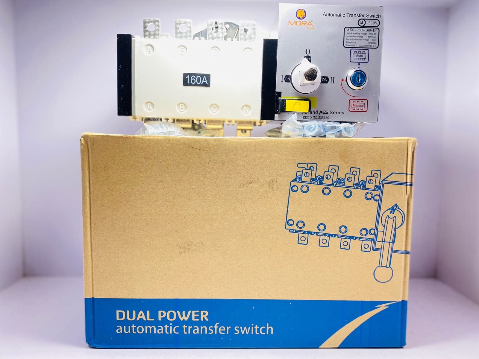
| Main 4P breaker, ATS, AC SPD | 1 each | From the load calculation (40–63 A class here) | See the load calculation post |
Staging plan: the 2 sidewall fans start first (stage 1), then tunnel fans in pairs, each pair a few seconds after the last. That way the generator sees the starting surge of only two 1.1 kW motors at a time instead of ten. The University of Kentucky’s poultry guide on backup systems for poultry houses also stresses that ventilation must keep working even if the main controller fails, which is exactly what the Hand position and a backup thermostat give you.
Phase balance: every three-phase fan draws equally from L1, L2 and L3, so the fans balance themselves. Put single-phase loads (lights, controller, sockets) spread across the three phases, not all on L1.
Pakistan-specific problems and how the panel should handle them
| What happens on the farm | Likely cause | Panel fix |
|---|---|---|
| All fans restart together after load-shedding; generator stalls or ATS chatters | No staging | On-delay timers per stage or controller staging |
| Fan motor burns while “breaker didn’t trip” | Single phasing; MCB can’t see it | Overload per motor + phase failure / V/A protector |
| Overloads trip at 2-3 pm in June | Low voltage at peak raises motor current; dial set below FLC; dusty or slipping belt | Set dial to nameplate FLC; check voltage on panel meter; service fans |
| Contactor buzzes or chatters | Low control voltage or dust on magnet faces | Check control voltage at A1-A2; clean or replace contactor |
| Fans run backwards after generator work | Phase sequence swapped on one source | Match L1-L2-L3 order on WAPDA and generator sides of the ATS |
| Panel trips after cooling pad wash | Water entering through open cable holes | Glands, drip loop, panel away from pad spray |
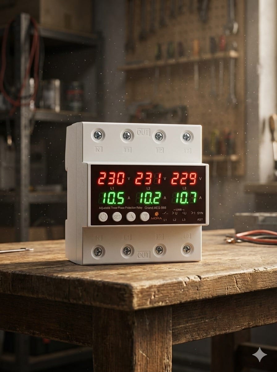
Single phasing is the most common silent killer on rural feeders. A MORA 100A three-phase voltage and current protector at the incomer watches all three phases and disconnects when one drops or voltage goes out of limits.
Safety notes
- Panel building and fault-finding on 400 V must be done by a qualified electrician, with the supply isolated and locked off, including the generator.
- Earth the panel body, door, every fan frame and the SPD to a tested earth pit.
- Use an RCCB on socket and lighting circuits where workers handle wet equipment.
- Never bypass an overload “because it keeps tripping”. Find the reason: voltage, jammed blade, loose belt or wrong setting.
- Label every MCB, contactor and selector with the fan number, and keep a printed diagram inside the panel door.
Exhaust fan control panel checklist
- ☐ Fan nameplate current noted for every motor
- ☐ One MCB, AC-3 contactor and overload (or MPCB) per fan
- ☐ Overload dial set to nameplate FLC, not “a bit higher”
- ☐ Coil voltage matches the 230 V control circuit
- ☐ Controller outputs switch coils only; interposing relay where needed
- ☐ Hand-Off-Auto on every fan or stage, tested in Hand
- ☐ Staged restart after WAPDA or generator returns
- ☐ Phase failure / V/A protector, ATS and SPD at the incomer
- ☐ Same phase sequence on WAPDA and generator
- ☐ Run/trip lamps and an alarm the farm staff can hear
- ☐ Sealed cable glands, panel away from cooling-pad spray
You can find contactors in our magnetic contactors range, LED run/trip indicator lamps, and a full farm product list on the poultry farm electrical and solar solutions page.
FAQ: exhaust fan control panel for poultry shed
Which contactor is best for a poultry exhaust fan?
Choose a contactor whose AC-3 (motor) rating is comfortably above the fan’s nameplate current, with a coil voltage that matches your control circuit. For a common 1.1 kW, 2.5 A fan, a 9 A AC-3 contactor such as the Schneider LC1D09 is a good fit.
What should the overload relay setting be for an exhaust fan?
Set the overload dial to the full-load current printed on the motor nameplate. Choose an overload whose adjustable range covers that value, for example a 2.5–4 A range for a 2.5–2.6 A fan.
Can one contactor run several exhaust fans?
It can switch them, but each motor still needs its own overload or motor protection breaker. One overload on a group cannot detect one jammed or single-phased motor.
Why do all fans trip when WAPDA comes back after load-shedding?
Usually because all fans start at the same moment and the combined starting current trips the main breaker or stalls the generator. Stage the restart with on-delay timers or the controller’s staging feature.
Can I wire the fan directly to the climate controller?
No. Controller relay outputs are meant to switch contactor coils, not motors. Wire the controller output to the contactor coil through the Auto position of a Hand-Off-Auto selector.
Get your shed panel parts list checked
Send us your fan count, motor nameplate photos and shed layout on WhatsApp. Hum aapko contactors, overloads, MCBs, selectors, phase protector aur ATS ki complete list bana kar denge, with genuine brands and supply across Pakistan. WhatsApp HN Electric: 0329 1654950
