


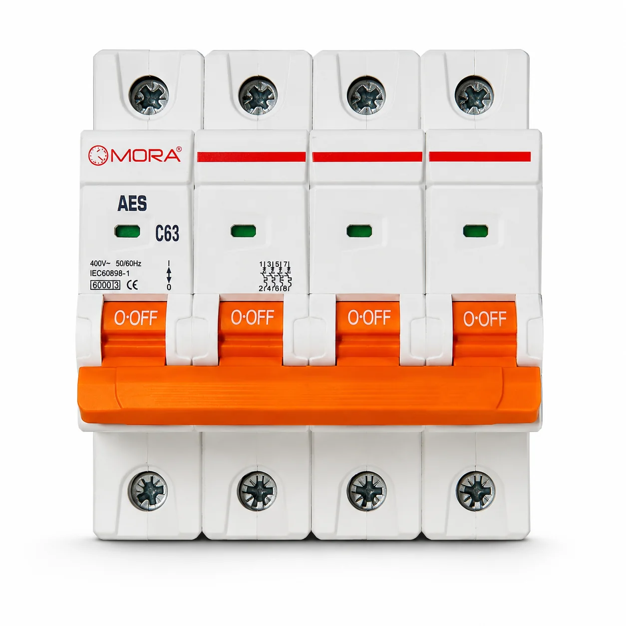
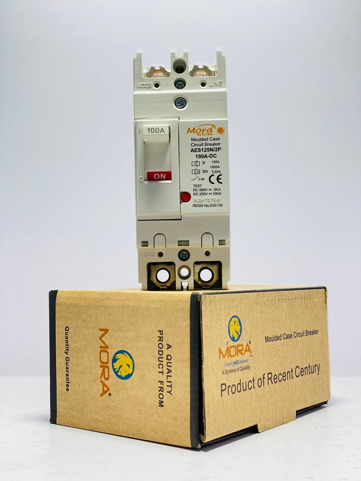
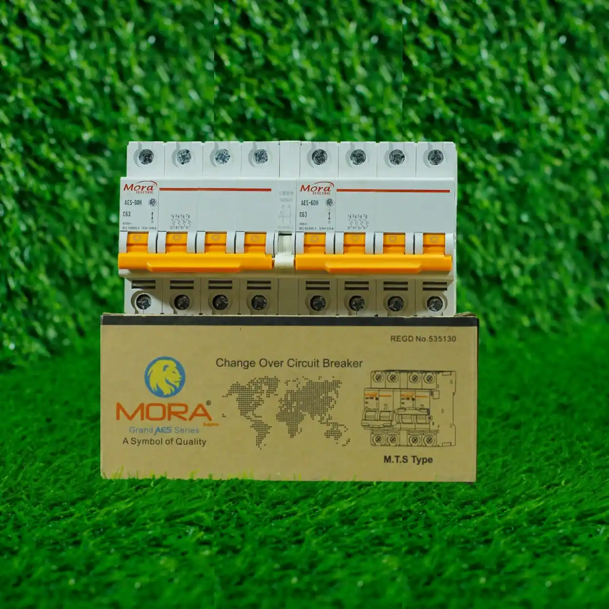

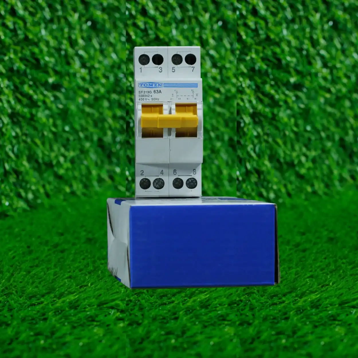








Setting Digital Protector Voltage and Current Limits


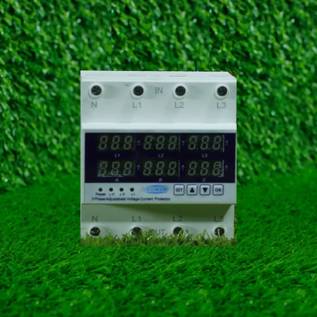
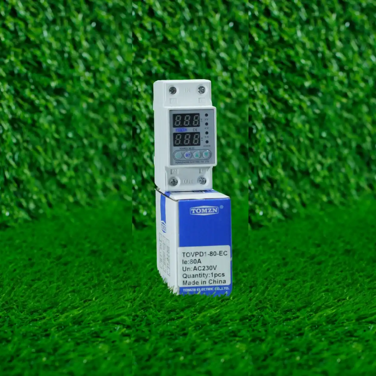
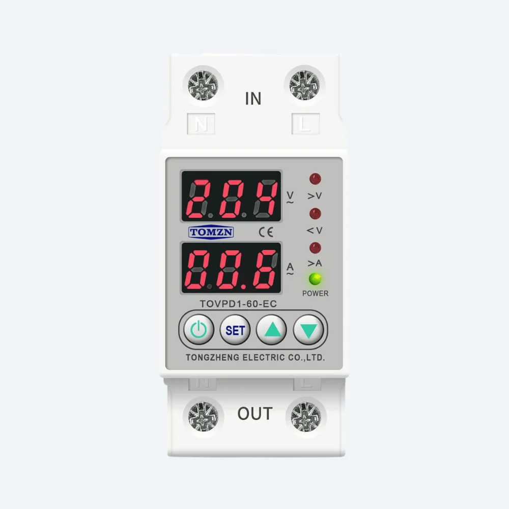
Last month a customer from Model Town brought in a three-phase TOMZN protector that kept nuisance-tripping on his 15kW poultry farm load. Turns out he’d set the current limit at 40A on a panel feeding a 10HP motor, two water pumps, and some lighting on a single-phase tap. The protector wasn’t faulty, he just didn’t understand why the settings mattered or how to configure them properly for his actual load profile. This is more common than you’d think, and it’s exactly why I’m writing this.
A digital protector does nothing useful if you set it wrong. It will either nuisance-trip and anger your customer, or fail silently when it should kick in. Either way, you’ve wasted the component and lost trust. Setting safe voltage and current limits sounds like a simple calibration task, but it requires you to understand what’s actually happening on site, what the protector is designed to do, and what Pakistani WAPDA supply really looks like.
Understanding What a Digital Protector Actually Does
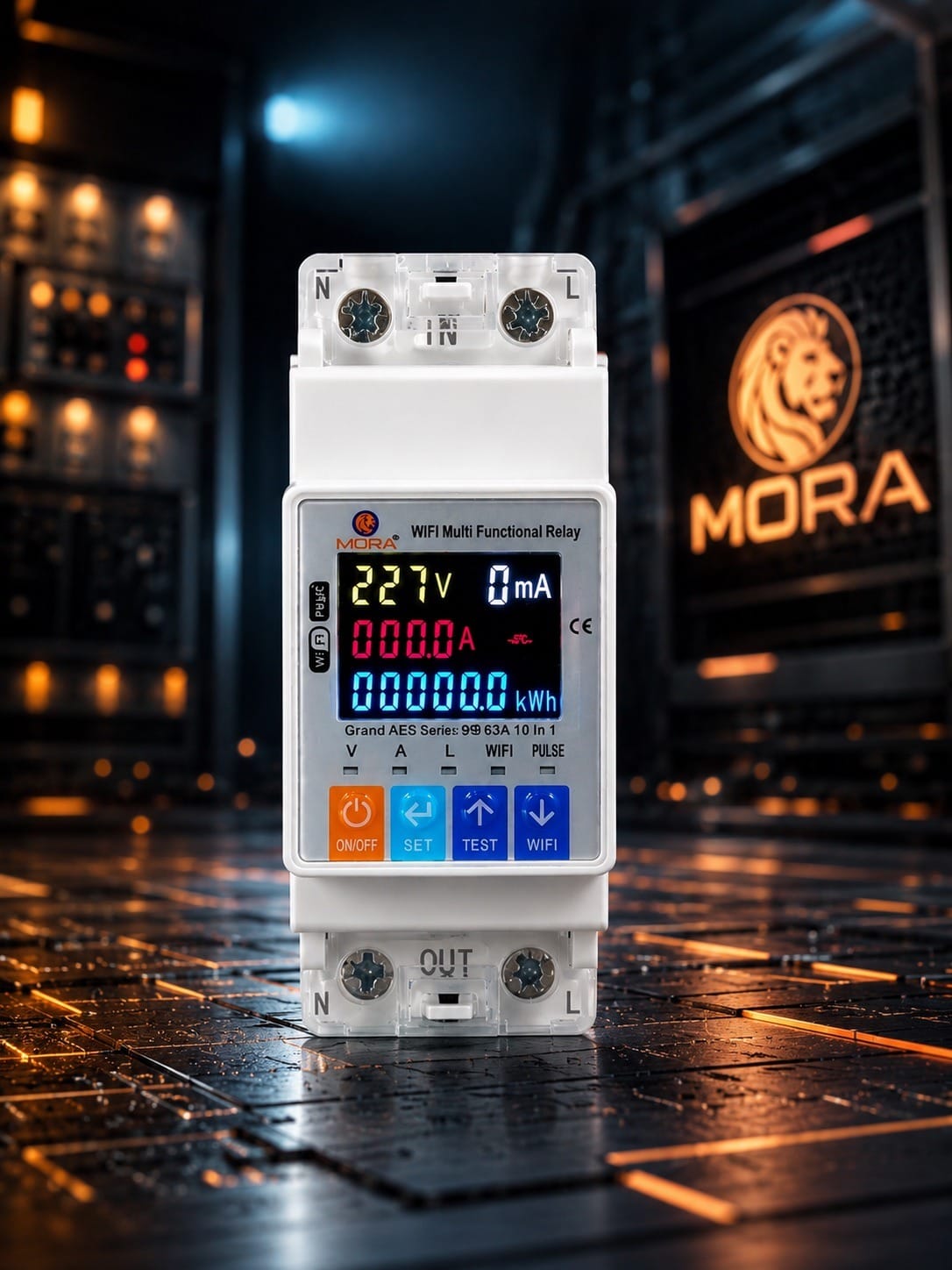
A digital protector monitors two things: the voltage coming in from WAPDA (or your generator or solar inverter), and the current flowing through the circuit it’s protecting. When either goes outside the safe range you’ve set, the protector trips the load or signals an alarm. That’s it. No magic, no guesswork.
On residential sites, most digital protectors protect against overvoltage (when WAPDA surges above 250V on single-phase), undervoltage (when load-shedding or a fault drops it below 160V), and overcurrent (when someone plugs in too many appliances or there’s a short circuit). On commercial or farm sites, you’re also protecting three-phase motors from phase imbalance and phase failure, which can destroy a motor winding in minutes if you don’t catch it.
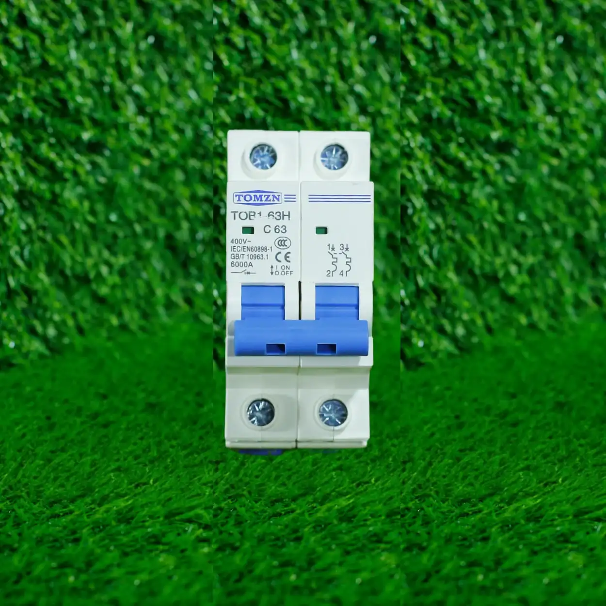
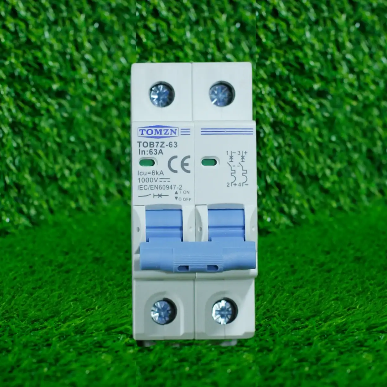
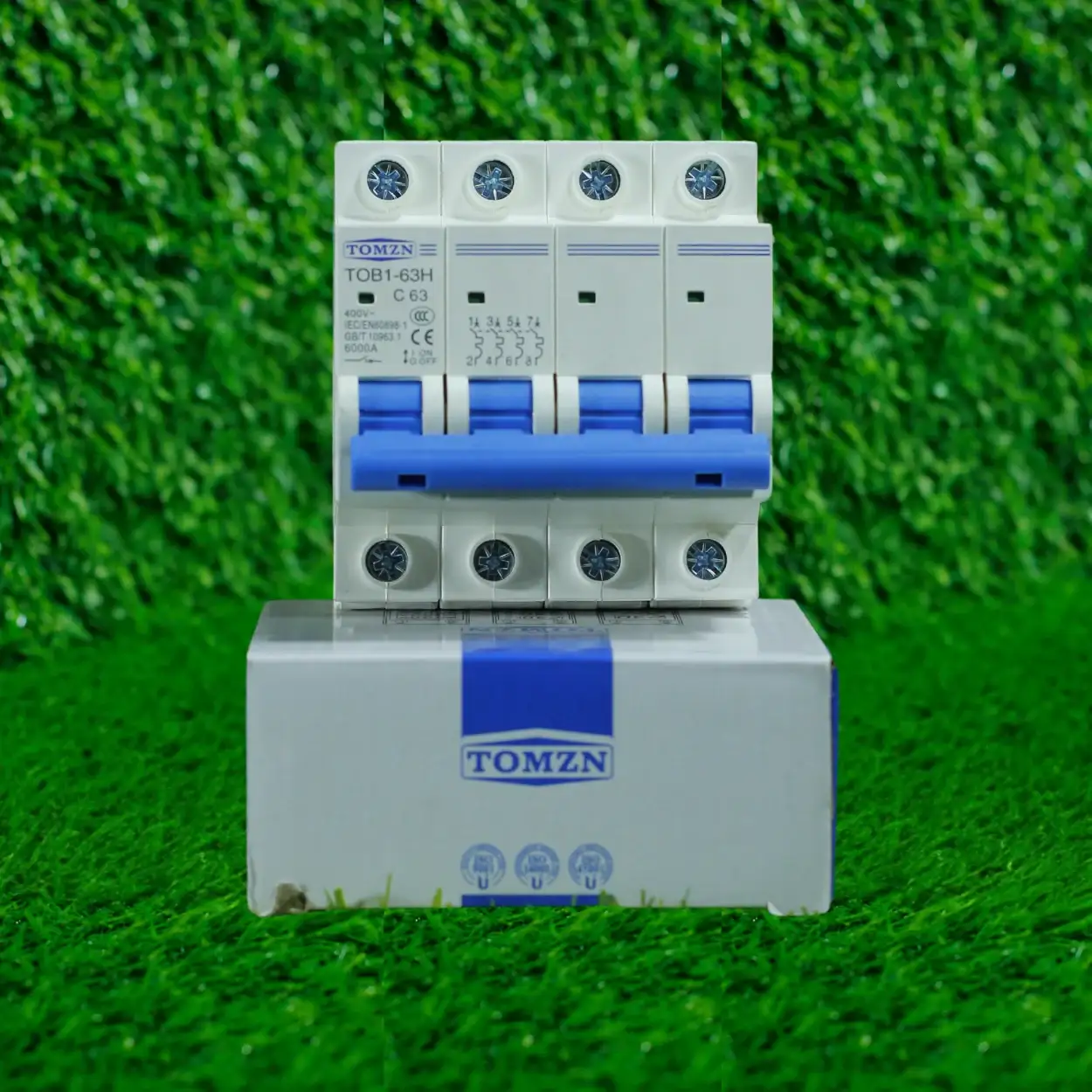
The protector doesn’t replace a circuit breaker or RCCB. It works alongside them. A breaker handles the mechanical disconnection and carries the fault current safely to ground. A protector is the intelligence that tells the breaker when to trip.
Setting Voltage Limits for Pakistani Supply Conditions
WAPDA nominal supply in Lahore and most of Punjab is 220-230V single-phase and 380-400V three-phase at 50Hz. In theory. In practice, you’ll see swings from 180V up to 260V on a single day, depending on load demand, transformer tap settings at the pole, and how far your property is from the distribution transformer. I’ve measured 265V on summer afternoons and 155V at 6 PM during peak load-shedding.
Most digital protectors let you set an overvoltage trip point and an undervoltage trip point separately. Here’s what I recommend based on site conditions:
- Overvoltage (upper limit) for single-phase: Set between 245-250V. Above 250V, you’re risking capacitor banks in split ACs, motor windings, and LED drivers. I’ve seen capacitors literally blow open at 260V. Some protectors let you set a warning threshold at 240V and a trip threshold at 250V, which is ideal if the feature exists.
- Undervoltage (lower limit) for single-phase: Set between 160-170V. Below 160V, three-phase motors start to stall and can overheat. Single-phase compressors and water pumps struggle. If you set it too high (say 190V), you’ll nuisance-trip during normal load-shedding and frustrate the customer. I went to 180V on a Model Town site and it cut nuisance-trips by half.
- Three-phase overvoltage: 450V max (that’s roughly 260V per phase).
- Three-phase undervoltage: 320V minimum (roughly 180V per phase).
These ranges assume you’ve verified the actual supply voltage at the meter during different times of day. Don’t just guess. A decent multimeter or a voltage protector with display will show you what you’re actually working with. I’ve walked onto jobs where the customer complained about constant tripping, measured the supply, and found it was sitting at 265V all day. In that case, you might need a voltage stabilizer upstream of the protector, not just limit adjustment.
Setting Current Limits Based on Your Actual Load
This is where most people get it wrong. They look at the breaker rating or the wire size and set the protector current limit to match it. That’s backwards. The current limit should match your actual expected load, not the maximum the wire can handle.
Let’s say you have a 63A main breaker (common in Lahore residential). That breaker is sized so the wire won’t melt if 63A flows through it. But your actual house load is maybe 30A on average (lights, fans, one AC, kitchen appliances). If you set the protector current trip at 63A, it will only kick in if something goes badly wrong, like a short circuit right at the load, and by then the wire is already hot and the breaker will have to do the work anyway. You’ve wasted the protector’s ability to catch an overcurrent early.
Better approach: Measure or estimate your actual peak load, add a 20-30% safety margin, and set the current trip there.
On the poultry farm I mentioned at the start, the customer had a 15kW load. That’s roughly 65A at 220V single-phase (P = V x I, so 15,000W / 220V). He was running all three loads occasionally (motor, two pumps, lights), but not simultaneously. His simultaneous peak was closer to 12kW, or about 55A. So I set the protector at 60A. If he genuinely needs all three to run together someday, he’d need to upgrade the supply line and transformer, not lower the protector trip point.
For three-phase loads, do the same calculation using the three-phase formula: P = 1.732 x V x I x power factor. Assume a power factor of 0.9 for motors and inductive loads. If it’s unclear, ask the customer or look at their WAPDA bill, which usually lists average load.
Time Delay and Nuisance-Tripping
Many digital protectors let you set a time delay on the current trip, usually 1-10 seconds. This exists because inrush current (the surge when a motor first starts) can briefly exceed your normal running current by 3-5 times. Without the delay, the protector trips the moment you turn on the pump or motor, even though everything is fine once it’s running.
I typically set a 2-3 second delay on protectors guarding motors or heavy inductive loads. For resistive loads (heaters, ovens) or anything without a motor, 1 second or no delay is fine. Some protectors let you set different delays for overvoltage and overcurrent separately, which is better because overvoltage shouldn’t have a delay (it’s always a fault), but overcurrent can tolerate a short delay to let inrush current settle.
During commissioning, I always test the delay. Turn on the heaviest single load the protector will see (usually the biggest motor), watch it for 5 seconds, and confirm it doesn’t trip. If it does, increase the delay by 1 second and try again. This takes maybe 2 minutes and saves hours of callbacks.
Phase Failure and Phase Imbalance on Three-Phase Circuits
Three-phase protectors, like the TOMZN TOVPD3-VA, usually include detection for phase failure (one of the three supply lines is dead or disconnected) and phase imbalance (voltages between phases differ significantly). These are separate from the voltage and current limits I mentioned earlier.
Phase failure protection should always be ON. If one phase dies, a three-phase motor will try to run on two phases, stall, draw excessive current, and burn out in minutes. The protection should trip immediately with no delay. Most protectors default to this, but check.
Phase imbalance detection is usually set to trip if any phase differs from the average by more than 5-10%. This catches situations where one phase is heavily loaded (say, a neighbor’s welder or agricultural pump is pulling hard on one line) and starves your motor. Again, this should usually be ON unless you’re in an area with chronic phase imbalance issues and the customer accepts the risk (which is rare and not smart).
What Settings to Write Down and Hand Over to the Customer
After you install and configure the protector, document the settings you used and why. Not on a WhatsApp chat that gets lost, but on a label stuck to the protector or a printed sheet given to the customer. Include:
- Overvoltage trip point (in volts)
- Undervoltage trip point (in volts)
- Overcurrent trip point (in amps)
- Time delay for overcurrent (if any)
- Phase failure: ON or OFF
- Phase imbalance: ON or OFF (if three-phase)
- The date of installation and your name/contact
This protects you later. If the customer adjusts settings on their own and something trips, you have documentation of what you set. If a protector fails, the manufacturer can see the configuration and determine if it was misused.
Common Mistakes I See in the Field
Setting overvoltage too high (260V or more) because the customer doesn’t want it to trip during a surge. That’s the opposite of what they should want. The protector should trip at a surge to protect the load downstream.
Setting current limit equal to the breaker rating. As I explained, this makes the protector useless.
Not testing after installation. I’ve walked onto callbacks where a protector was installed months ago, and when I tested it, the time delay was so short that it nuisance-tripped on motor startup. The customer assumed the protector was faulty when it was just misconfigured.
Installing a protector without also upgrading the RCCB or main breaker. A protector tells you there’s a fault, but if the downstream breaker is undersized or corroded, it won’t trip cleanly. You need both working together.
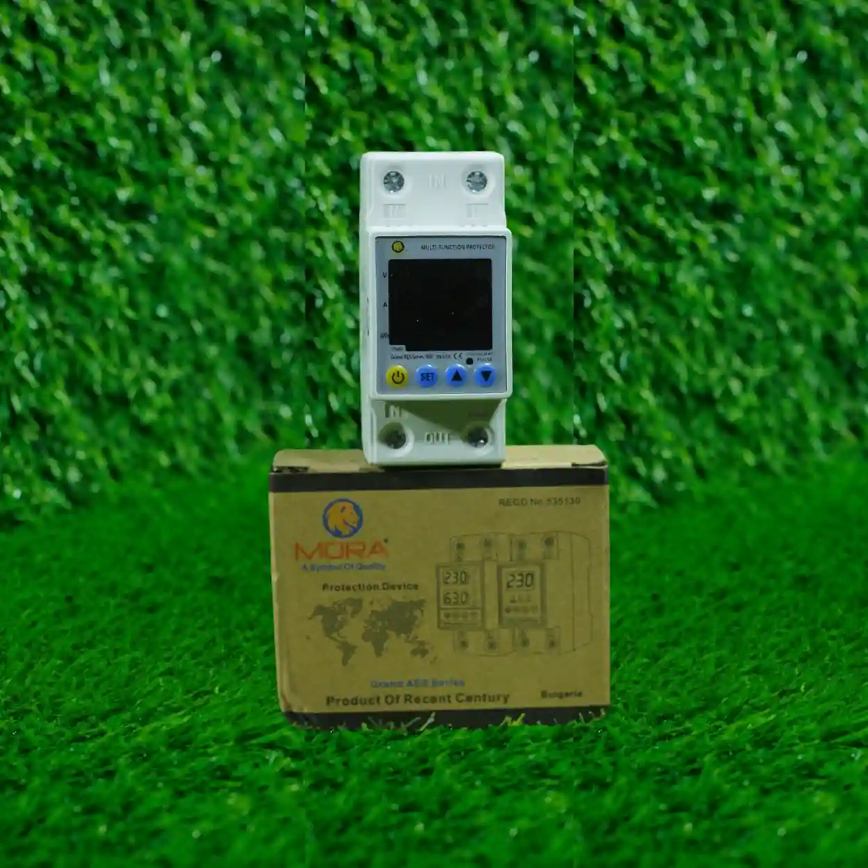
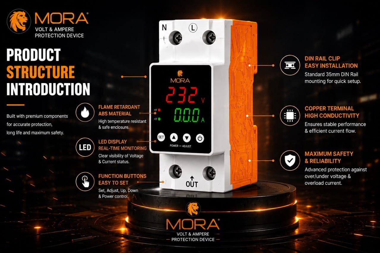
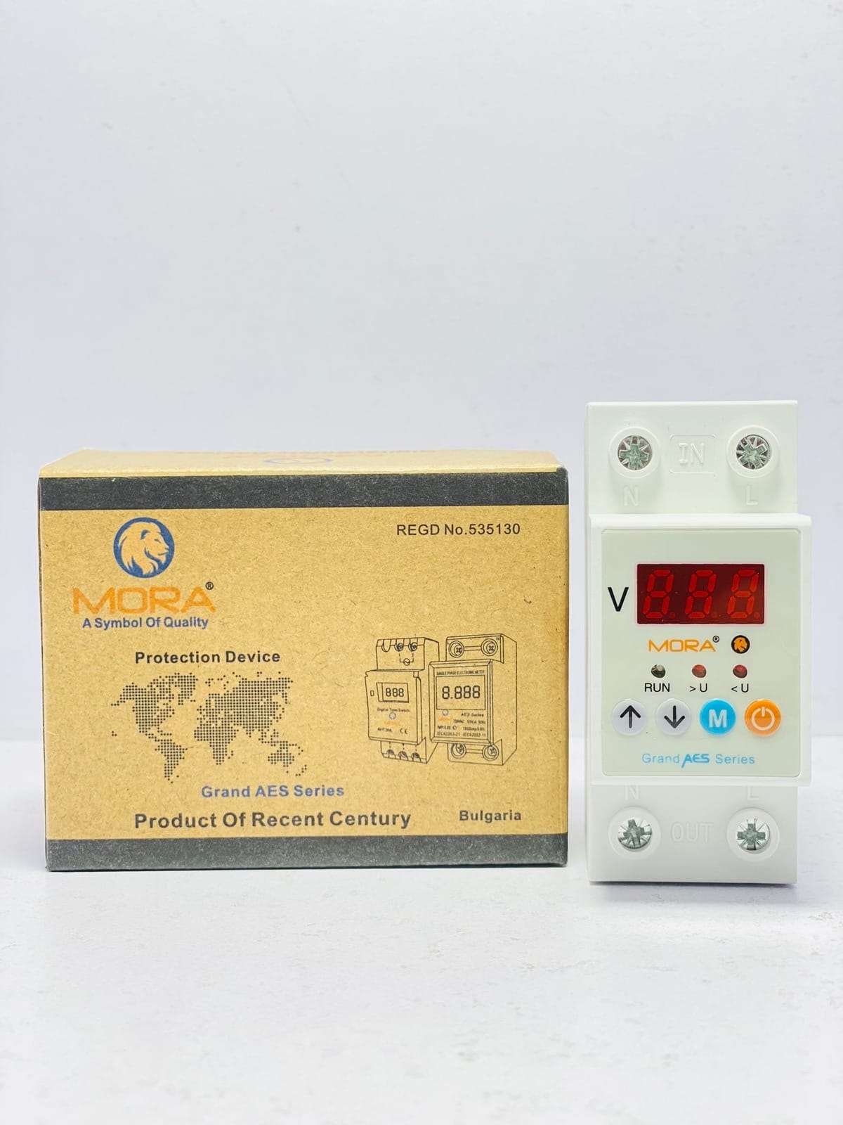
Buying a cheap knockoff protector from a parts market and expecting it to hold calibration. I’ve tested TOMZN and MORA units months after installation and they stay within 5% of calibration. Some no-name units drift 15-20% in a season. You get what you pay for.
Getting This Right Saves You Callbacks
Setting voltage and current limits correctly is not complicated, but it requires you to understand the site, the load, the supply conditions, and the customer’s tolerance for nuisance-tripping versus protection. A 15 minute conversation before configuration, plus 5 minutes of testing during installation, will eliminate 90% of the callbacks and complaints you’d otherwise get. It also builds credibility with customers, because you’re clearly thinking about their specific situation, not just slapping a device on a panel and hoping it works.