
Star Delta Starter Wiring Diagram: Power & Control Circuit, Timer and Overload Setting (Pakistan)


Short answer: a star delta starter wiring diagram has two parts. In the power circuit, the supply goes through an MCCB and the main contactor (KM1) to motor terminals U1-V1-W1, while the other three ends W2-U2-V2 go to a star contactor (KM3) that shorts them together for starting, and a delta contactor (KM2) that connects them back to the three phases for running. In the control circuit, START latches KM1, the star-delta timer holds the motor in star for a few seconds, then drops KM3 and picks up KM2. KM2 and KM3 must never be on together, and the overload relay is usually set to about 0.58 × the motor’s full-load current.
This guide gives you an original power diagram, a control wiring diagram with timer, a sizing chart for contactors and overload, a worked example for a 400V tubewell motor, and the mistakes we see most often in Pakistani panels. Everything here is for 400V three-phase supply from LESCO, MEPCO, FESCO, IESCO or any WAPDA DISCO, or from a generator.
What a Star Delta Starter Does (in Plain Words)
A three-phase induction motor started direct-on-line (DOL) pulls a big rush of current for the first few seconds. On a weak rural feeder or a generator, that rush makes lights dim, trips the upstream breaker or makes the voltage dip so much that other machines drop out.
A star delta starter cuts that rush by starting the motor with its windings in star (Y). In star, each winding gets 400 ÷ 1.732 ≈ 230V instead of 400V, so the starting current from the line and the starting torque both fall to about one-third of the DOL value. Once the motor has nearly reached full speed, the starter switches the windings to delta (Δ), where each winding gets the full 400V and the motor can give full torque.
| Point | Star (Y) – starting | Delta (Δ) – running |
|---|---|---|
| How winding ends are joined | W2, U2, V2 shorted together (star point) | U1-W2, V1-U2, W1-V2 (closed loop) |
| Voltage across each winding | ≈ 230V | 400V |
| Line current | ≈ 1/3 of DOL starting current | Normal full-load current |
| Torque | ≈ 1/3 of DOL starting torque | Full rated torque |
| Contactors closed | KM1 + KM3 | KM1 + KM2 |
Check the motor plate first
Star delta starting only works if the motor is designed to run in delta at your supply voltage. On a 400V supply, the nameplate should show something like 400V Δ / 690V Y (some older plates say 380V Δ / 660V Y), and the terminal box must have six terminals. A plate that says 230V Δ / 400V Y means the motor runs in star on 400V; if you try to star-delta it, the windings will see too much voltage in delta and burn. Many small motors are wound this way, so read the plate before you buy a starter.
Star Delta Starter Wiring Diagram: Power Circuit

Follow the diagram from the top:
- Q1 – MCCB or motor-rated breaker. Takes R, Y and B from the supply and protects the whole starter against short circuit. See our MCB vs MCCB guide if you’re not sure which type to use.
- KM1 – main contactor. Its output feeds the motor’s start ends U1, V1, W1. KM1 stays closed in both star and delta.
- F1 – thermal overload relay. Fitted on KM1’s output, in the leads going to U1-V1-W1. In this position it measures winding (phase) current, not line current, which is why its setting is 0.58 × FLC (explained below).
- KM2 – delta contactor. Its line side is tapped from KM1’s output: R, Y, B. Its load side goes to W2, U2, V2. When KM2 closes, R joins U1 to W2, Y joins V1 to U2 and B joins W1 to V2. That is delta.
- KM3 – star contactor. Its input is also W2, U2, V2, and its output terminals are bridged together. When KM3 closes, the three winding ends are shorted into a star point.
Remove the factory links from the motor terminal box. All six ends must come to the starter, so you need two 3-core cables (or six single cores) between panel and motor.
Rotation tip: keep the same phase order on KM1 and KM2. If the delta connection is wired the wrong way round, the motor sees a different phase sequence when it changes over; it jerks hard at changeover, draws a big current spike and may trip. Check that the motor turns the same way in star and in delta before connecting the pump or fan.
Star Delta Starter Control Wiring Diagram with Timer

Most contactors sold in Pakistan for motor panels have 220V AC coils, so the control circuit is usually taken from one phase and neutral through a small control MCB. If your coils are 400V, take two phases instead. Never mix coil voltages in one panel.
- Line → control MCB → overload NC (95-96) → STOP (NC) → START (NO). The overload contact and STOP button are in series, so either one cuts every coil.
- KM1 seal-in. A normally open auxiliary contact of KM1 (13-14) is wired across the START button. Once KM1 picks up, it holds itself in after you release START.
- Timer KT (A1-A2) is fed from the same latched point, so it starts counting when KM1 picks up.
- Star coil KM3 is fed through the timer’s star contact (15-16, closed while timing) and a normally closed auxiliary of KM2.
- Delta coil KM2 is fed through the timer’s delta contact (15-18, closes after the time) and a normally closed auxiliary of KM3.
A dedicated star-delta timer opens 15-16 first and closes 15-18 after a short built-in gap, so the star contactor’s arc is out before delta closes. A plain on-delay timer doesn’t give that gap, which is the usual cause of a “bang” and a flashover on changeover. The two NC auxiliaries are the electrical interlock; a mechanical interlock clipped between KM2 and KM3 is the second layer. Use both, because KM2 and KM3 closed together is a dead short across the phases.
Terminal numbers like 15-16-18 are the most common marking, but some timers use different numbers or two separate outputs. Always follow the diagram printed on your timer.
How to Size the Contactors, Overload and Breaker
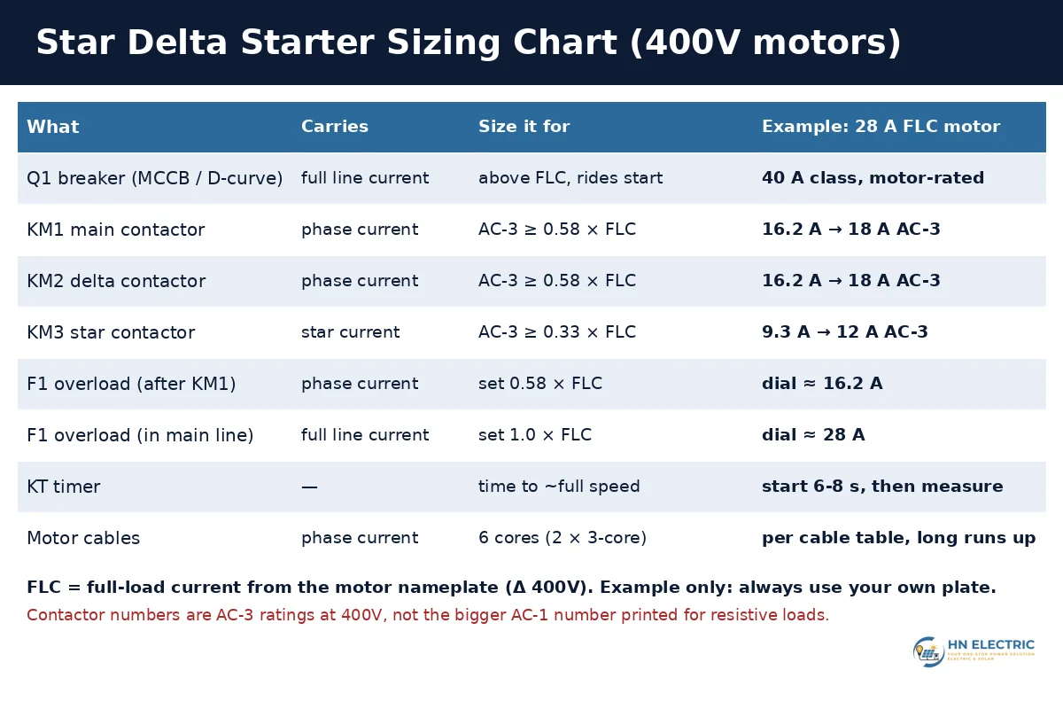
This is where most competitor pages go wrong. They tell you to size every contactor and the overload on the motor’s full-load current (FLC). In a star delta starter, the main and delta contactors only carry the winding current, which is FLC ÷ 1.732 ≈ 0.58 × FLC, and the star contactor carries about one-third of FLC during the start. That’s why star delta starters can use smaller contactors than a DOL starter for the same motor.
| Part | Current it carries | Rule |
|---|---|---|
| KM1 main contactor | Winding current | AC-3 rating ≥ 0.58 × FLC |
| KM2 delta contactor | Winding current | AC-3 rating ≥ 0.58 × FLC |
| KM3 star contactor | Star current (short time) | AC-3 rating ≥ 0.33 × FLC |
| Overload in winding leads (after KM1) | Winding current | Set ≈ 0.58 × FLC |
| Overload in main line (before split) | Line current | Set = FLC |
| MCCB / breaker | Line current | Above FLC, with a curve that doesn’t trip on the start current |
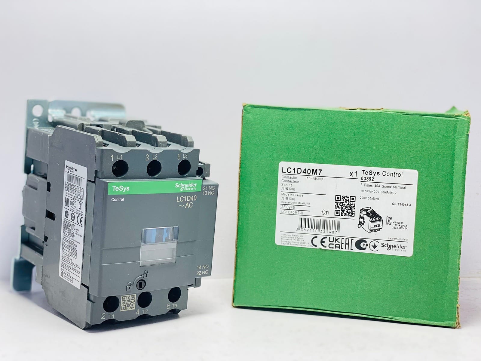
Two more points. First, always read the AC-3 rating (motor duty), not the bigger AC-1 number printed for resistive loads. For example, our Schneider LC1D12 is listed at 25A, which is its AC-1 rating; for motor duty it’s a 12A AC-3 contactor. Second, Siemens’ own star-delta starter instructions say the overload in this position should be set to 0.58 times rated motor current and never higher (Siemens operating instructions). Setting it at full FLC there means it will never trip on a real overload.
Worked example: 400V tubewell motor with 28 A on the plate
Say the plate on a submersible or surface tubewell motor reads 400V Δ and 28 A full-load current (this is only an example; use your own plate).
- Main and delta contactors: 0.58 × 28 = 16.2 A. The next AC-3 size up is 18 A, so a Schneider LC1D18 for KM1 and KM2. If the motor runs long hours in a hot pump room, many panel builders go one size up for margin.
- Star contactor: 0.33 × 28 ≈ 9.3 A. A 9 A contactor is too tight, so use 12 A AC-3 (LC1D12).
- Overload relay: after KM1, so choose a range that covers 16.2 A and set the dial to about 16.2 A.
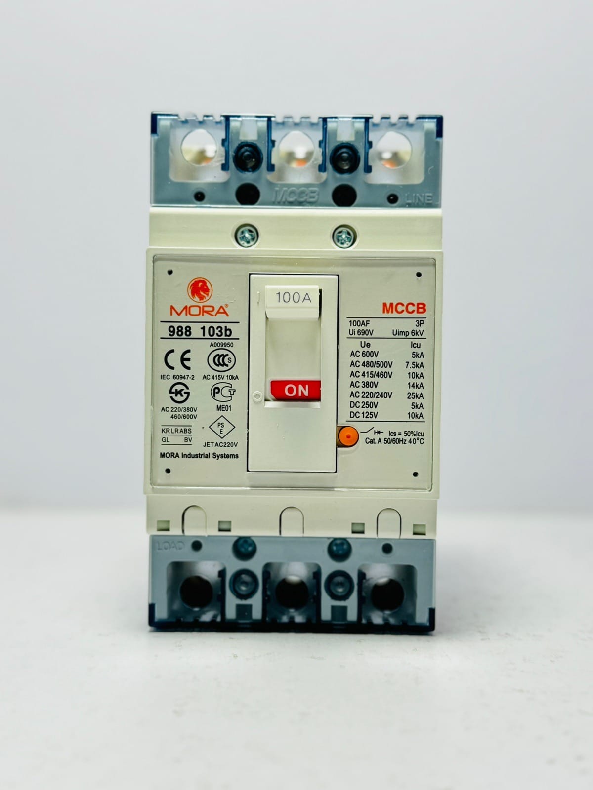
- Breaker: a motor-rated MCCB or D-curve breaker above 28 A that rides through the star start, for example the 40 A class. Check the trip curve against the motor’s start; our MORA 3-pole MCCB range covers larger motors and sub-main feeds.
- Timer: start at 6-8 seconds, then measure (see below).
How to Set the Star Delta Timer
The timer should hold the motor in star until it has nearly reached full speed. Switching too early gives almost the same current spike as DOL; switching too late keeps the motor at one-third torque for too long and it heats up.
- Set the dial to the starting time on the motor plate if it is given. If not, start with about 6-8 seconds, which is what Siemens’ starter instructions suggest when the time is unknown.
- Start the motor with a clamp meter on one phase. Watch the current fall as the motor speeds up, and listen for the hum to settle to a steady pitch.
- Note the time it takes to settle, stop the motor and set the timer to that value (a second more is fine).
- Restart and check that the changeover is smooth, with only a short kick on the clamp meter.
Pakistan note: motor torque falls with the square of the voltage. On a rural feeder that drops well below 400V in the evening peak, the motor takes longer to speed up in star. If your motor sometimes changes over while still slow, check the voltage at that time before adding more seconds.
Star Delta vs DOL vs Soft Starter vs VFD
| Method | Starting current (typical) | Starting torque | Best for | Watch out for |
|---|---|---|---|---|
| DOL | Highest, often 6-8 × FLC | Full | Small motors, strong supply | Voltage dips, breaker trips, belt/coupling shock |
| Star delta | ≈ 1/3 of DOL | ≈ 1/3 of DOL | Pumps, fans, blowers that start light | Needs 6 leads and a Δ-400V motor; spike at changeover |
| Soft starter | Adjustable, smooth ramp | Reduced, adjustable | Pumps where water hammer is a problem | Heat in the panel; still full speed only |
| VFD | Lowest, close to FLC | Good, controlled | Speed control, energy saving, solar pumping | Higher cost, needs correct sizing and filtering |
Star delta suits loads that start light: centrifugal pumps, tubewells, cooling-tower fans and big poultry-shed fans. It is a poor choice for loads that need high torque from standstill, such as a loaded conveyor or a compressor that starts against pressure. For more on motor starting basics see motor controller (Wikipedia).
Protection to Add in Pakistani Conditions
- Phase failure and low/high voltage: a missing phase or very low voltage burns more motors than overload does. A three-phase protector such as the MORA 100A 3 phase voltage and current protector cuts the supply when a phase drops or voltage goes out of range.
- Load-shedding restarts: with START/STOP push buttons and a seal-in, the motor will not restart by itself when power returns. That is safer. If you replace the buttons with a float switch, pressure switch or timer for automatic running, add a restart delay so every motor on the line doesn’t start at the same moment when power comes back.
- Generator supply: a star delta starter makes life easier for the generator, but the changeover kick is still there. Size the generator for the motor plus the rest of the load.
- Earthing: earth the panel body, the motor frame and the cable armour. Metal pump rooms with wet floors are high-risk.
If you are building a full panel for fans, see our exhaust fan control panel guide, and for single-phase motors and appliances, read protection devices for ACs, motors and fridges.
Common Star Delta Faults and What They Mean
| Symptom | Likely cause | What to check |
|---|---|---|
| Bang or flash at changeover | No gap between star and delta; plain timer used | Use a proper star-delta timer; check interlocks |
| Big kick and trip at changeover | Timer too short or delta phase order wrong | Measure run-up time; check U1-W2, V1-U2, W1-V2 |
| Motor hums in star, won’t speed up | Phase missing, very low voltage or load too heavy | Voltage on all 3 phases; pump/valve condition |
| Overload trips after a few minutes in delta | Overload set too low, or motor really overloaded | Clamp current vs 0.58 × FLC per lead |
| Overload never trips, motor burns | Overload set at full FLC in winding leads | Reset to 0.58 × FLC |
| Motor stops when START is released | Seal-in contact not wired or wrong (NC used) | KM1 13-14 across START |
Installation Checklist
- Motor plate says Δ at 400V and has six terminals; factory links removed.
- Contactors chosen by AC-3 rating: main and delta ≥ 0.58 × FLC, star ≥ 0.33 × FLC.
- Overload placed after KM1 and set to 0.58 × FLC (or FLC if it’s in the main line).
- Coil voltage matches the control supply (220V or 400V); control MCB fitted.
- Electrical interlock (KM2 NC in KM3 coil line, KM3 NC in KM2 coil line) plus mechanical interlock.
- Proper star-delta timer, set by measured run-up time.
- Same rotation in star and delta checked with the load uncoupled.
- Phase failure / voltage protection and good earthing.
FAQs
Which HP motor needs a star delta starter?
There’s no single number in Pakistan. Advice online ranges from 5 HP to 15 HP and up, and some DISCOs or factory owners set their own limit. As a practical rule, think about star delta (or a soft starter or VFD) once DOL starting dims the lights, trips breakers or strains the generator. The motor must also be a 400V-delta, six-lead motor.
Why is the overload set at 0.58 of the motor current?
Because in the usual star delta wiring the overload sits in the leads to U1-V1-W1, which carry winding current, not line current. Winding current is line current ÷ 1.732, which is 0.58 × FLC. If the overload sits in the main line before the split, set it to the full FLC instead.
What is the timer setting for a star delta starter?
Set it to the time the motor takes to reach nearly full speed. If you don’t know that yet, start with 6-8 seconds, then measure with a clamp meter and adjust. Light pumps and fans often need less; heavy fans with big blades often need more.
Can I use 220V coil contactors in a star delta starter?
Yes. Most contactors sold for motor panels in Pakistan have 220V coils. Feed the control circuit from one phase and neutral through a control MCB. Just make sure the timer and all three contactors use the same coil voltage.
Star delta starter motor kyun garam hota hai?
The most common reasons are: the timer is too long, so the motor stays in star at low torque; the overload is set wrong; one phase is weak or missing; or the load is heavier than the motor rating. Check the voltage on all three phases, the timer setting and the running current in each lead.
Need Parts or a Panel Checked?
HN Electric supplies genuine magnetic contactors, MCCBs, three-phase protectors and panel parts across Pakistan. Send a photo of your motor nameplate and your panel on WhatsApp 0329 1654950 and we’ll suggest the right contactor sizes, overload range and protection. Motor ki plate ki photo bhejein, hum sahi starter parts bata denge.
