










Rotary Changeover Switch: When and How to Wire One Right


A customer walks into the shop last week with a generator sitting in his truck and a half-finished house panel in Lahore. ‘I need something that switches from mains to generator without electrocuting anybody,’ he says. That’s a rotary changeover switch. Not a smart WiFi relay. Not an ATS with microcontroller logic. A physical rotary switch that mechanically breaks one supply before making the other. It’s the simplest, oldest, and most reliable solution for load-shedding Pakistan, and it’s still here because it actually works.
What a Rotary Changeover Switch Actually Does
A rotary changeover is a manual or semi-automatic selector switch that connects your load (lights, fans, fridge, whatever’s plugged in) to either WAPDA supply or a generator. The key word is ‘breaks before makes’ (or ‘break-make’ sequence). When you turn the handle from one position to the next, the switch physically disconnects the first supply completely before connecting the second. This prevents the two supplies running in parallel, which would trip breakers, damage equipment, or worse, back-feed into the WAPDA line and kill a lineman.
The switch has three positions typically: WAPDA (or ‘Mains’), OFF, and Generator (or ‘DG’). Some have only two live positions with OFF as a neutral center. The handle is mechanical and usually requires a deliberate turn, not accidental flicking. In newer installations, you’ll see semi-automatic versions where a relay senses mains failure and triggers the switch mechanically, but the core principle stays the same.
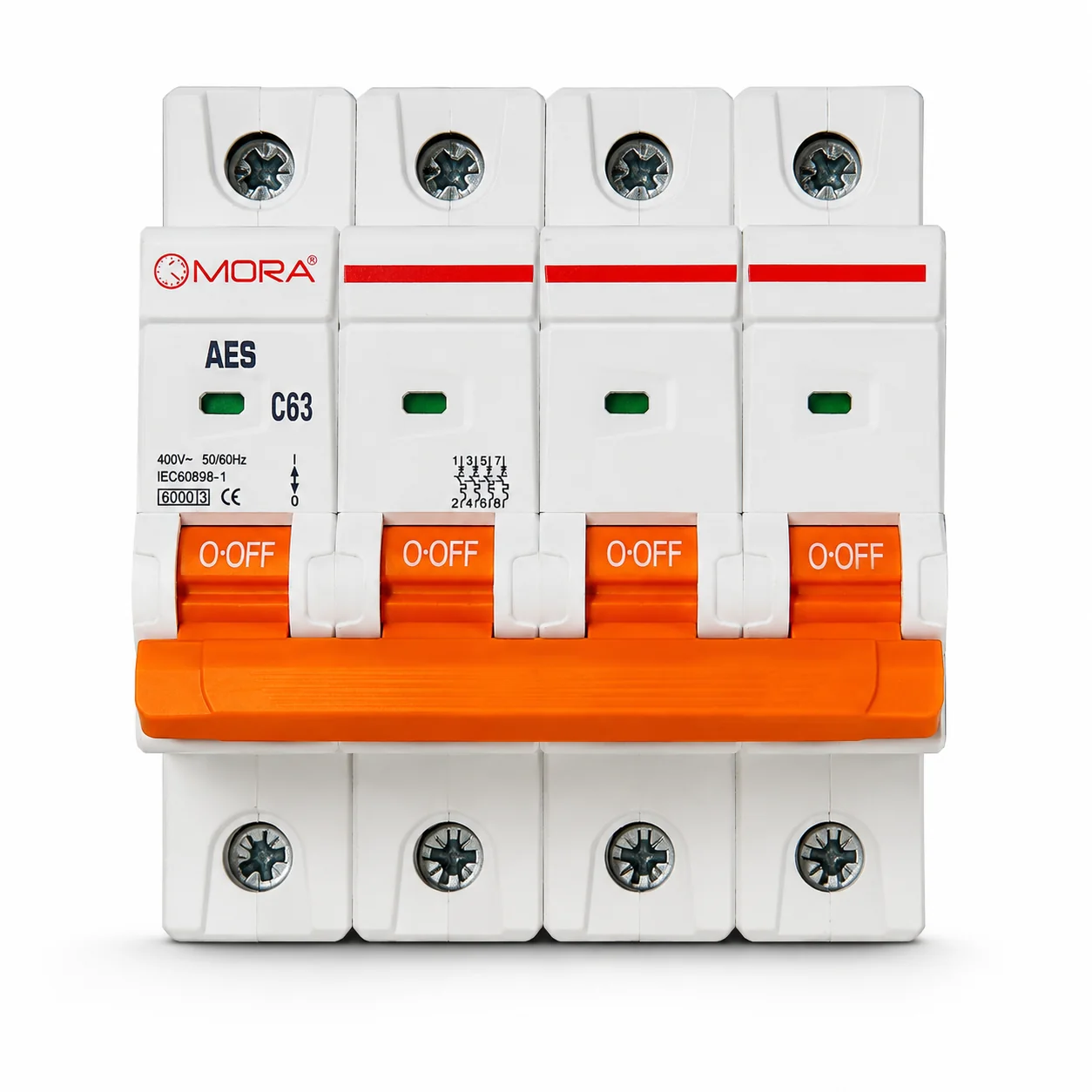
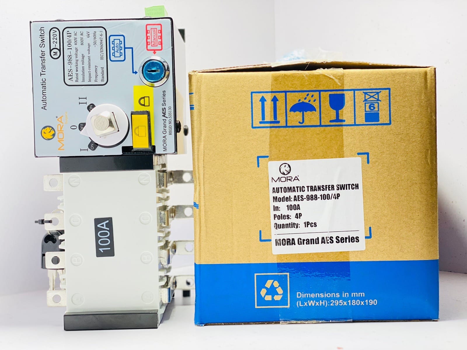
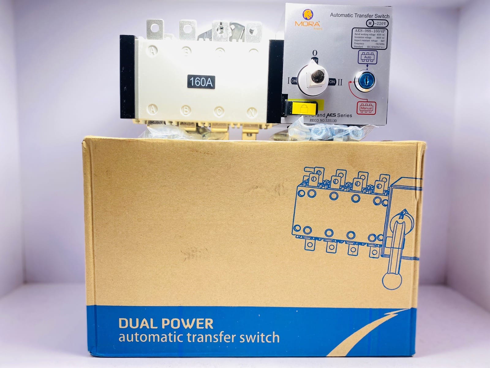
Current rating matters here. A household rotary changeover on a single-phase 220V supply typically runs 63A, 100A, or 125A depending on load. For three-phase industrial or large poultry-farm setups, you’re looking at 160A, 200A, or higher on a three-pole unit rated for 380-400V. The switching contacts themselves need to handle the inrush current from motors and compressors, not just steady-state amperage.
Common Applications on Pakistani Sites
You’ll see rotary changevers in almost every house with a generator in Punjab and Sindh. Residential, agricultural, small commercial, backup for UPS and solar inverters. The load-shedding culture made this switch essential. Before automatic transfer switches became common and affordable, every installation was rotary manual. Many still prefer it because there’s nothing to malfunction, no transformer to burn out, no relays to get stuck.
On poultry farms, I’ve wired dozens of them. A 100A rotary handles the main feed from generator to the farm panel, and then individual circuits branch off to fans, feeders, heaters, whatever. The switch sits visibly at the entrance, and the farmer or manager rotates it when WAPDA comes back on. Simple. On a solar installation with a battery backup, the rotary switch might sit between the grid, the solar inverter, and a backup generator, though this setup needs more care because three separate supplies can create confusion.
The rule is straightforward: if you have two independent supplies and need to pick one at a time without any automatic logic, a rotary changeover is the honest choice. It costs less than an automatic transfer switch (ATS), lasts longer, and doesn’t require a control transformer or auxiliary power supply. In rural areas where WAPDA voltage might be 180V on a bad day or 245V on a good one, you don’t need sensitive electronics to get confused; a rotary switch just moves the connection and doesn’t care about voltage swings.
Wiring: The Core Principle and Site-Specific Traps
The wiring is not complicated, but mistakes here can be lethal or at least destroy equipment fast. Here’s the layout: WAPDA supply comes in on one terminal, generator on another, and the load circuits branch from a third common point. The switch shaft mechanically connects one input to the output, and when you rotate it, the output disconnects first, then reconnects to the other input.
On paper, it’s simple. In the field, three things go wrong regularly:
- Neutral bonding confusion. In a typical 220V single-phase setup in Pakistan, you have live (L), neutral (N), and earth (E). Some installers wire both the live and neutral through the rotary switch. That works if the switch is rated for it, but many small rotary units are only rated to switch the live conductor. The neutral should be common to both supplies and bypass the switch entirely. You bond the neutral from WAPDA and the generator at one point (usually the main panel), and both neutrals continue straight to the load without switching. I’ve seen jobs where the neutral was switched and caused phantom voltages and tripping faults that took hours to diagnose.
- Earth continuity. The earth conductor must never be switched. It goes straight from the earth terminal of WAPDA supply, bonds to the earth terminal of the generator, and continues to the load and the main earthing electrode (or at least a good earth connection at the panel). If you’re using a standby generator, you need to make sure the generator frame is also bonded to the same earth point. On jobs where this wasn’t done, I’ve seen nuisance shocks from the panel enclosure when the generator was running.
- Load side wiring confusion. Some panels have the rotary switch on the load side of the main breaker, some have it before. If it’s after the breaker, the breaker trips if there’s a short on the load side, and the switch is safe. If the switch is before the breaker, you need to make sure both the WAPDA and generator feeds have their own protection (either separate breakers feeding the switch, or a built-in protective element in the switch itself). Most commercial rotary changeovers come with integral breaking capacity (typically 3kA to 10kA for household units, higher for industrial), which means the contacts themselves can handle a short-circuit to a degree, but you don’t want to rely on that. Wire it such that each incoming supply has a protective device upstream of the switch.
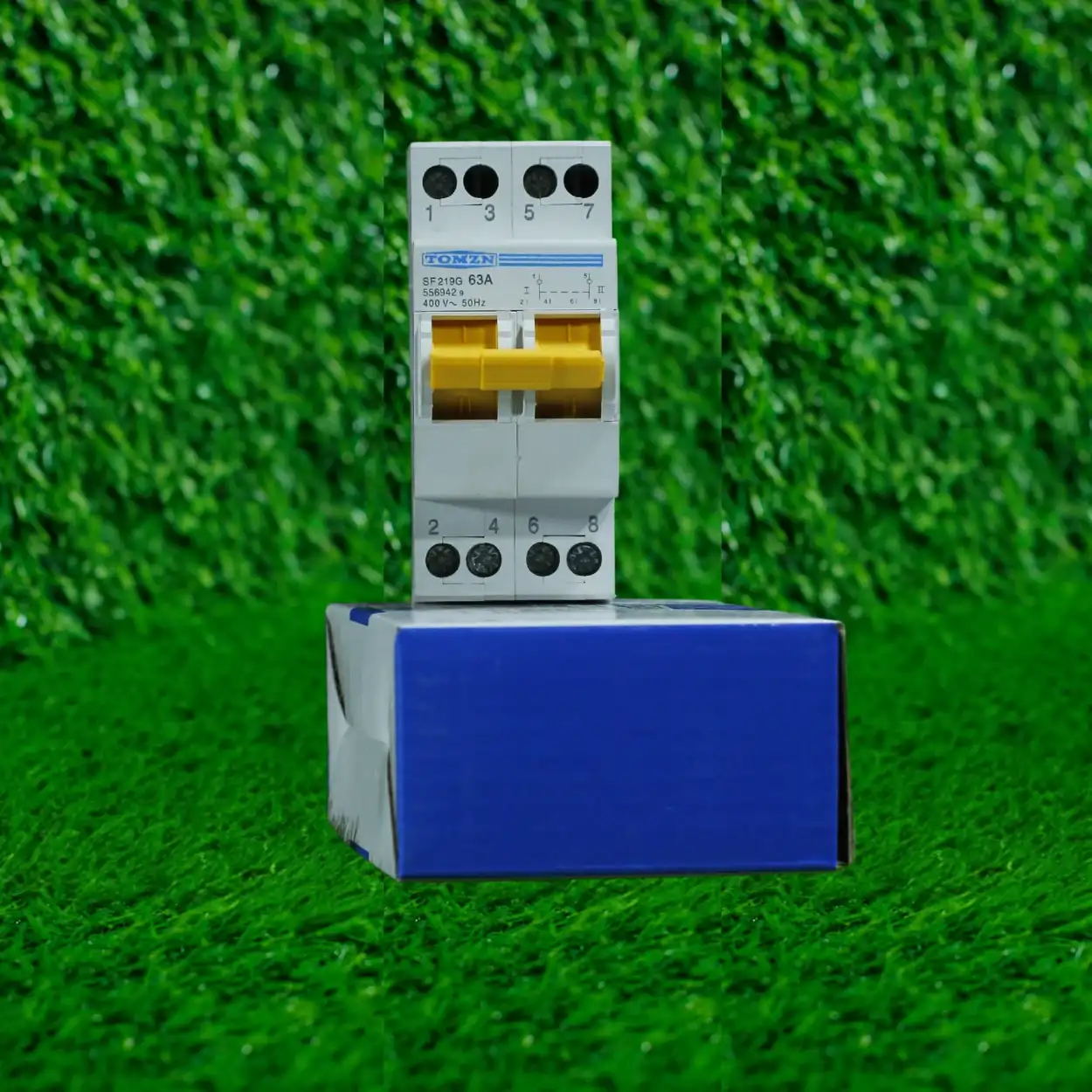
Here’s what I do on every job: I run the WAPDA live and earth to terminals 1 and 3 of the switch, the generator live and earth to terminals 2 and 4, and the common output (to the load) from terminals 5 and 6. Neutral bypasses the switch entirely and is bonded at the panel. The load-side breaker (usually a 100A MCB or MCCB) sits right after the switch output and protects everything downstream. This way, there’s no ambiguity, and if I hand over the panel to someone else five years later, the wiring is unmistakable.
Manual Versus Automatic (Semi-Automatic) Switching
A pure manual rotary switch requires someone to physically walk to the panel and turn the handle when WAPDA fails or returns. On a house, that’s annoying but doable. On a poultry farm with 15,000 birds, a power cut at 2 AM without someone to switch the generator on means dead birds by morning because the exhaust fans stop and temperature spikes. So semi-automatic rotary switches exist.
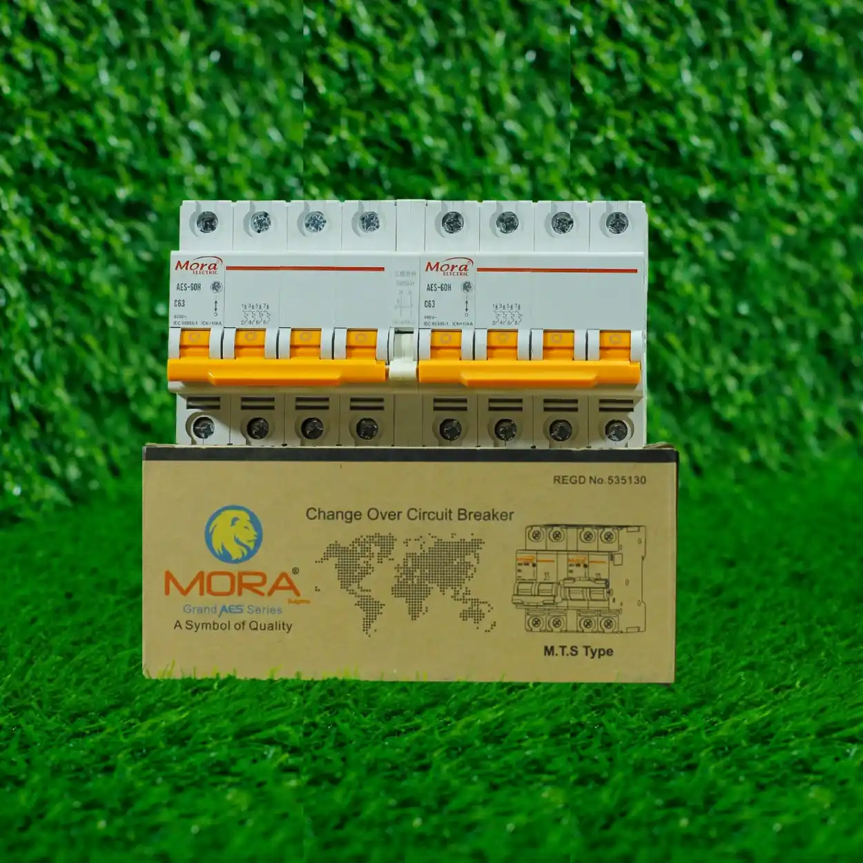
These use a relay circuit that detects mains failure (voltage drop below a set threshold, usually around 180V on a 220V supply) and triggers a solenoid or motor to turn the switch handle mechanically. The relay circuit needs a small auxiliary power supply, often 12V DC or 24V DC drawn from a battery or a small transformer-rectifier unit. When WAPDA comes back, another relay or timer waits a few seconds (to avoid switching back into a brown-out) and triggers the switch to return to mains.
The advantage is obvious: no human intervention needed. The disadvantage is that the relay circuit, transformer, and solenoid add cost, complexity, and failure points. I’ve seen relay coils burn out from voltage spikes during load-shedding transitions, and transformers fail from heat in poorly ventilated panels. For a critical load like a poultry farm, it’s worth it. For a house with a generator as a convenience, a manual switch and some discipline is often cheaper and more reliable.
On solar inverter setups in Lahore and Islamabad, I’ve wired both manual and semi-automatic versions. The semi-automatic is popular because the homeowner doesn’t want to fuss with it during a WAPDA cut, especially if they’re relying on solar + battery backup with a generator as a fallback. The sequence is typically: solar + battery running the house, WAPDA fails, solar takes over (automatic), battery runs down, relay switches to generator (semi-automatic), and when battery recharges, it switches back to solar. This needs careful sequencing to avoid the generator and solar inverter fighting each other, but a properly configured rotary switch with the right relay logic handles it.
Protecting the Changeover and What Fails in Practice
The rotary switch itself is a durable mechanical device, but the contacts wear over time, especially if you’re switching frequently (which happens a lot in Pakistan during heavy load-shedding seasons). After a few years of daily switching, the contacts develop a thin layer of oxidation, and the resistance increases. In extreme cases, the switch gets warm or doesn’t make good contact with the load side, causing voltage drop and nuisance faults downstream.
I’ve also seen corrosion inside the switch enclosure on jobs where the panel sits in a damp or dusty environment without adequate ventilation. The metal parts of the switch corrode, the contacts pit, and eventually the switch fails to hold load or gets stuck partway between positions. Prevention here is basic: choose an IP65-rated enclosure for outdoor or damp locations, ensure adequate ventilation inside the panel (but not so much that dust blows in), and inspect the switch contacts every few years if the installation sees heavy use.
One real scenario I handled: a large dairy farm in Okara had a 100A rotary switch that I installed about eight years prior. During a particular load-shedding season, the switch was being rotated multiple times per day. The customer called saying the generator runs fine but won’t take full load through the switch; lights are dim, motors won’t start. I went out, measured the voltage at the load side while the generator was running through the switch, and got 195V instead of the expected 220V. The switch contacts were so oxidized that they were drawing about 25V across the contact resistance. Cleaned the contacts with fine steel wool, reset the switch, and voltage came back to 215V (generator voltage is always a bit lower than WAPDA, but this was acceptable). The fix lasted another few years until the customer replaced the switch proactively.
To prevent this, use a rotary switch rated for your exact current load (don’t oversize thinking it’ll last longer; undersizing causes arcing and rapid wear, but oversizing is wasteful and doesn’t improve longevity). Ensure the incoming WAPDA and generator supplies are at similar voltage levels; if the generator consistently runs at 200V and WAPDA is 230V, the mismatch stresses the switch and increases inrush currents. And have the switch contacts inspected during routine maintenance.
Coordinating with Breakers and Protection Devices
Your rotary changeover is not a protective device; it’s a selector. It needs protection upstream and downstream. On the upstream side, the WAPDA feed should have a main breaker or fuse at the meter (WAPDA typically provides this), and the generator should have its own main breaker before feeding the switch. On the load side, after the switch, you need a main breaker (typically 100A or 125A MCB or MCCB for a household setup) that protects all the circuits downstream.
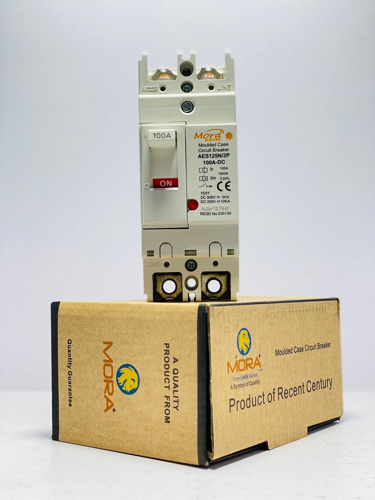
The breaking capacity of these breakers must coordinate with the breaking capacity of the rotary switch itself. Most 100A residential rotary switches have a breaking capacity of 3kA to 6kA, meaning they can safely clear a fault current up to that level without the contacts fusing or the switch enclosure rupturing. The main load-side breaker should be rated to handle the maximum fault current available from either supply (WAPDA or generator) and should trip faster than the switch contacts would burn. In practice, for residential setups in Lahore on a standard WAPDA 220V supply with a 5-10kW generator, a 100A MCB with 6kA or 10kA breaking capacity on the load side of the switch is sufficient.
If you’re installing surge protection (lightning protection or transient voltage surge suppression), place it on both the WAPDA and generator input sides of the switch, or use a device like a surge protector rated for AC mains on the load side after the switch. This prevents spikes from either supply reaching your equipment.
Three-Phase Rotary Changevers for Industrial and Farm Loads
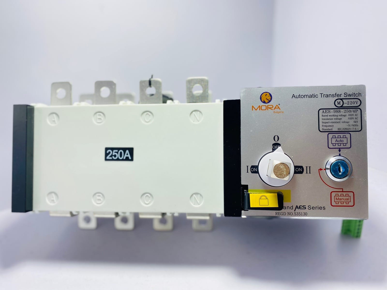
A three-phase rotary changeover is larger, heavier, and more complex than a single-phase unit because it has to switch all three live conductors simultaneously, maintain phase sequence, and handle the higher fault currents of a three-phase supply. Typical ratings are 160A, 200A, or 250A at 380-400V for industrial poultry farms or large agricultural operations.
The wiring principle is the same, but you’re working with L1, L2, L3, neutral, and earth for both WAPDA and generator inputs. The switch must maintain proper phase sequence; if the generator is out of phase with WAPDA, switching between them can cause a massive inrush current and trip the main breaker or damage motors. To avoid this, most installers either manually phase-check the supplies before connecting a new generator, or use a phase-sequence relay downstream of the switch that won’t allow motor loads to run if the phase sequence is wrong.
On a three-phase farm, the rotary switch typically sits at the main panel entry, and 160A or 200A is common for an operation running multiple fans, feeders, and pump motors. I wired one on a broiler farm near Sheikhupura that runs a 60kW generator (which is roughly 100A at 380V), and the 160A three-phase rotary switch handles it comfortably with a 160A main breaker downstream and individual branch circuits for each load area.
What to Ask Before Buying or Specifying
When you walk into a supplier to get a rotary changeover, or when you’re specifying one for a new panel, know these details: (1) voltage and frequency of your supply (220V single-phase 50Hz or 380V three-phase 50Hz in Pakistan), (2) rated current at that voltage (63A, 100A, 125A, or higher), (3) whether you want manual or semi-automatic, (4) breaking capacity required (typically 6kA for household, 10kA for commercial), and (5) whether you need an IP65 enclosure if it sits outdoors or in a dusty environment.
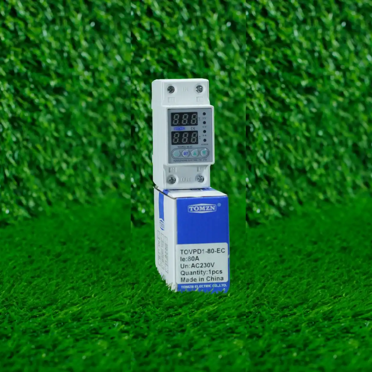
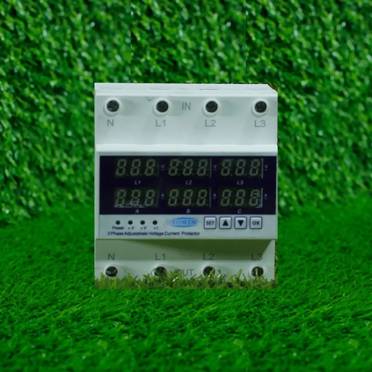
Brands like TOMZN and other legitimate manufacturers make solid rotary switches at reasonable prices in the Pakistani market. Avoid the deep-discount knockoffs from random Chinese suppliers; the contacts and mechanical tolerances on cheap units are loose, and they fail within a year or two of heavy use. A genuine 100A rotary switch from a known brand costs between 4,000 and 8,000 PKR depending on whether it’s manual or semi-automatic, and it’ll last 8 to 12 years on a typical residential setup with moderate switching cycles.
For a farm or commercial application with higher duty cycles, budget for replacement every 5 to 7 years or have spare contacts on hand. Many switches have replaceable cartridges or contact sets, which costs half the price of a new unit and takes an hour to swap out if you know what you’re doing.
If you’re pairing the rotary changeover with a solar inverter and battery system, make sure the inverter documentation explicitly allows a rotary switch between the grid and the inverter’s AC input. Some inverters expect a utility input with certain voltage stability and won’t handle the switching transients well. Modern inverters with built-in ATS functions might render a separate rotary switch redundant, so check before buying both.
The rotary changeover switch is not glamorous, and it won’t appear in any automated home-automation setup. But it’s proven, affordable, and reliable in Pakistani conditions where load-shedding is frequent and grid stability isn’t guaranteed. Properly wired with correct protection and regular maintenance, it’ll switch your load between WAPDA and generator for over a decade without fuss. That’s why it’s still here, and why it will probably still be here in another decade.
Related products at HN Electric
- MORA 50A 2 Pole Rotary Change Over Switch
- MORA 75A 2 Pole Rotary Changeover Switch
- Mora 3P 75A Rotary Changeover Switch
- MORA 125A 4 Pole Changeover Switch
- MORA 32A 3 Pole Change Over Switch
Browse the full range: Change Over Switches